Putsch® Pressure Leaf Filter Installation and Results


Waste water regulations require minimizing impacts to surface and ground water including lime pond systems. Western Sugar Cooperative’s Fort Morgan factory installed three Putsch® PKF-140 pressure leaf filters to replace the existing rotary vacuum drum filters. This change allowed the lime cake to be handled on a dry basis where the drum filters required the cake to be slurried and pumped to a pond. This was a rare environmental project that had return as the lime sewer loss was reduced from 0.15-0.20% OB to 0.03% OB. The installation design and start up issues with the project will be detailed. The first three months of operational performance will be discussed
Fort Morgan De-Sweetening Filter Station Modernization
The Fort Morgan Factory of the Western Sugar Cooperative was built by the Great Western Sugar Company in 1906. The factory has operated every year but one since then. The factory currently has a slice capacity of 6000 TPD and produces around 1,680,000 pounds of sugar per day. As part of a modernization and environmental project, a new de-sweetening filter station was installed at the factory over the 2012 summer.
The Fort Morgan factory has a BMA extraction tower and cossette mixer installed in 1996 supplied by Putsch® table slicers dating to the early 1990’s. Fort Morgan operates with a typical purification system consisting of a 4 cell Mueller prelimer that has been operated both hot and cold and it is currently being operated fairly hot at 75 C. This is followed heat exchangers heating the juice to 85 C, a main limer, and the first carbonation tank. The factory operates a gas fired lime kiln that provides 28-31% carbon dioxide. The first filtration is accomplished using a rapid settler similar to an Ice Clarifier or Enviroclear. The clarified juice is heated to 95 C for second carbonation and second filtration is completed using US filters. Second filters and third filters are sluiced to the main limer with the solids being removed in the first carbonation clarifier. A polymer is used to assist the settling in the first carbonation clarifier and the underflow is controlled to produce a lime slurry with 40-50% suspended solids. This is then the feed to the de-sweetening filters.
Existing Station
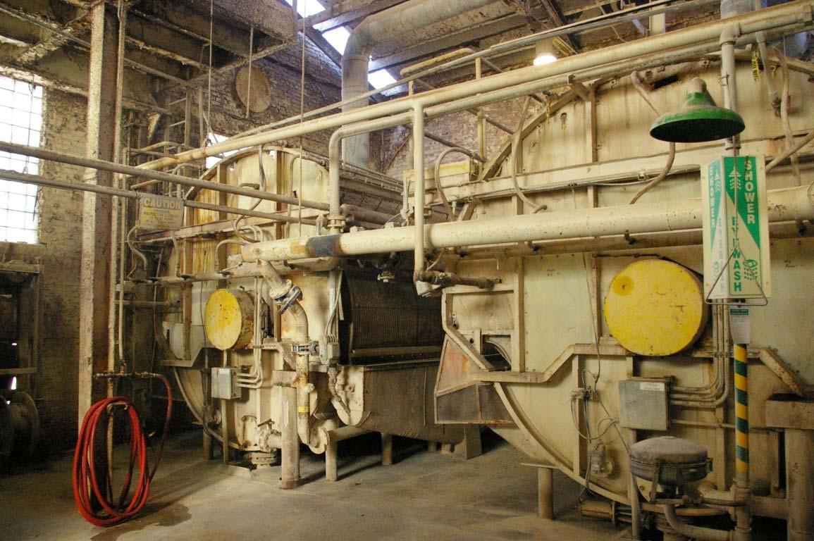
The existing de-sweetening station consisted of five each rotary vacuum drum filters, a condenser system with a Nash 2000 cfm vacuum pump and a slurry tank. The sugar laden slurry was pumped up to the drum filter station filling the tubs of the rotary vacuum filters. Excess feed overflowed the tubs to the feed tank. A condenser and vacuum pump were used to suck the feed against the drum filter clothes. The clothes retain the lime and sugar juice is pulled through to be recovered. The drum rotates where very hot wash water is applied. This displaces the remaining sugar water in the lime cake reducing the sugar loss to the lime. The rinsed cake is the discharged from the drum to troughs where it is slurried and pumped to the lime ponds. Typical results for drum filter operation in Fort Morgan where a sugar loss of 0.15%-0.25% on beets with a cake moisture level of 50-60%.
The rotary vacuum drum (RVD) filters and components were installed in the 1960’s and were near the end of their useful life. The filters were sensitive to the filterability of the juice andwere often the cause of the factory having to reduce slice. The RVD filter station was located on the 3rd floor of the main factory just to the west of the slicer station. The building dates to 1906 and on the north side of the station was the lime kiln and on the south side was the tower diffuser. To the west is the beet handling system with trash and rock catcher waste pick up. This area is very congested and it would be difficult to install the new station in this location. The station will produce 250-300 tons per day of precipitated calcium carbonate (PCC). Handling this many trucks in this small area would be difficult.
Project Goals
The primary goal for this modernization project is to eliminate the lime ponds to meet the new environmental requirements in Colorado. Fort Morgan has down gradient ground water monitoring wells that show the ground water meets all ground water standards, but the Department of Environmental Quality is insisting that any water entering an unlined pond must meet surface water quality standards. This assumes no treatment is accomplished in the pond or in situ, although the ground water monitoring wells indicate it does occur. Other goals included reducing the sugar lost to lime sewer, increasing the capacity of the station, and eliminating odors from the pond system.
The existing system was old enough with many cross ties within the factory that it was suspected that unaccounted for sugar was being lost. Both the flume water and the condenser water in Fort Morgan have a higher sugar content than customary. By replacing this station, it was hoped some of these losses would be eliminated.
Design Considerations
The station was designed for a slice rate of 6500 tons per day with a lime usage rate of 4.3% limestone on beets. Several pressure leaf filter manufacturers were considered. Although pricing was similar for all three brands, Putsch® was selected for this station due to its predominance in the US and European sugar industry. The station was then installed per all Putsch® recommendations. Some of the key components specified by Putsch® included Warman slurry feed pumps, double screw receiving hoppers and a separate first filtrate and sweet water recovery system.
Since the existing station location was not ideal, it was decided to install the filter station in conjunction with mud belt presses at a location near the flume water clarifier. Some of the reasons for this decision were:
- Using a common building provides the opportunity to minimize labor
- The “greenfield” installation allows uncompromised layouts and construction efficiency
- It is a lot easier to pump slurries and juices than to convey solids
- Truck traffic is moved away from congested areas providing employee and trucking safety
- The thick juice pipe rack could be utilized for 70% of the pipe run to and from the building
- The building is close the flume water clarifier allowing the mud press piping to be minimized
- The solids can use a common retaining wall saving costs
- The basic design can be used for other factories within Western Sugar including Billings in 2013 and Lovell and Scottsbluff in future years.
- The building is a long way for sampling and for supervisors, but it is close to the clarifier and flume water screening station so the added distance is not significant
- The location is close to the private tunnel under Interstate 76 that allows access to the long term storage area for the PCC and mud.
The equipment required for the pressure-sweetening filter station included 3 each Putsch® Model PKF-140 pressure leaf filters. These filters have 140 square meters of filter cloth area and include full automation. The filter area is filled using the Warman slurry pump on a variable frequency drive. This is programmed to completely fill the chamber with solids to ensure the cloth and bladder have even pressure and do not tear. The rubber bladder is then inflated to 130 psig to press the sugar water from the PCC cake. The sugar water pressed during this stage is the first filtrate. The air pressure is released and a fixed volume of hot water is pumped into this chamber. The air pressure is re-applied pressing the de-sweetening water from the cake. The sugar water pressed during this stage is the sweet water. The system has a tank and pump for both the sweet water and the first filtrate allowing the sweet water to be used for the slaker and the first filtrate to be returned to purification. Compressed air is then blown through the PCC cake to dry the cake to 68-70% dry substance.
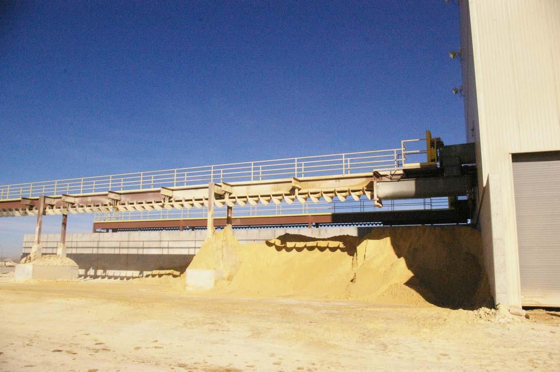
The dried cake is then released by using hydraulic cylinders to separate the leaves of the filter. The cake drops to the double screw hopper where two 20” diameter ribbon screws break up and conveyer the cake to the main conveyance system. The double screw hopper includes a drop to breaker bars designed to break up the PCC sheets and protect the screw conveyor shafts. The double screw hoppers discharge to 24” standard flight screw conveyor system. The final screw conveyor is trough-less and is 14’ above the stacking slab. The trough-less design allows for a continuous pile maximizing the storage on the pad. The PCC builds up to the screw and forms its own trough. This design also minimizes the amount of PCC that free falls minimizing the risk of entraining the PCC in the wind and causing dusting issues.
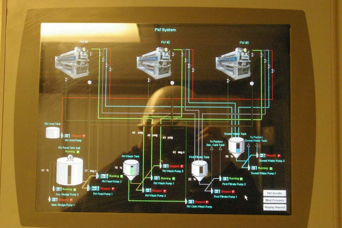
The Putsch® PKF-140 filters are fully automated. This includes an automatic cloth wash once every shift where high pressure (500 psig) wash water is used to wash each filter cloth automatically. Hydraulic cylinders open the leaves and sensors align the spray bar with each filter cloth. Each sequence of the filter is adjustable and automated. The sequences are adjusted using time, flow or pressure to ensure proper operation of the filter. The building also incorporated several interesting design features. The waste heat from the air compressors can be exhausted outside in hot weather, in the building in cold weather or in the air compressor room if needed. This adds dry heat to the building to keep these wet processes from causing condensation and corrosion on the building components. The building also has a drive through truck loading bay to load trucks without stacking, but this system has not been commissioned yet. Centrifugal pumps were used for all services allowing for standard maintenance and spares.Pumps were size for 1800 RPM service or lower where possible to provide longer service life and lower net positive suction head requirements with hot liquids.
System Performance
The mechanical installation was contracted while the electrical and instrumentation was installed by the Fort Morgan personnel and the non-Putsch® programming was completed by the Fort Morgan E&I supervisor. Due to other electrical and instrumentation project demands, the project was started in early November. The factory started slice in early September and operated for 50 days on the RVD filters until the new system was started. During this period, the factory operated on good quality beets and slice rates were not as high as normal due to other operational problems. In other words, the RVD filters were not pushed due to beet quality or capacity. During this time, the losses in the PCC were measured at 0.8 to 1.6% on sugar entering. When the new station was commissioned, the losses dropped to 0.10%.
During start up, the major start up issue was the PKF-140 discharge rate versus the screw conveyor capacity. Screw conveyors were chosen as conveyors because they can be sealed to minimize dust and vapors. The PCC is dried to 68-70% dry substance and it is about 80-85 C. At this temperature and dry substance, the PCC can cause dust issues and will release vapor. By using a screw conveyor that is well sealed, these issues are eliminated, but screw conveyor plugging and cleaning plugs can be an issue. The screw conveyors were sized for a 300% surge above the average flow rate for the PCC. The filters dump at 2000% the average. At start up, this difference in rates became apparent and the screw conveyors were sped up while the discharge rate of the press was slowed. This solved the problem and the conveyor system operated as designed after this point. The normal cycle time for these batch filters is 19-20 minutes and this was increase by about 1 minute with this change. The loss in capacity was not noticeable for the station.
Once the conveyor problem was solved, the new filter station operated continuously for the remainder of campaign with very few problems. The problems encountered included a few filter clothes that were cut (8-15) and we are working with Putsch® to solve this issue. The filter feed valves were high performance butterfly valves and the Teflon seats were cut. We will replace these with EPDM seated valves. The amount of sweet water was significantly reduced and the sugar in this water was reduced. The factory has not adjusted to this change and a permanent solution is being worked on.
The project also recovered sugar that was being lost to the condenser water system and to the flume water system. Both systems experienced a drop in the sugar concentration once the new filter system was started. The flume water concentration drop was small, but the condenser water sugar drop was significant. The unaccountable losses dropped 1.5% and this led to an extraction increase. Overall, the factories extraction increased 3% with 1.5% less PCC loss and 1.5% less unaccountable loss. The loss to the condenser system was most likely due to the high vacuum necessary to generate the capacity in the drum filters pulled sweet water to the condenser system.
The power requirements of the new system are greater than the RVD filter system. The RVD filter system used about 350 HP. The new system uses about 500 HP. This results in an additional power cost of $30,000 per year. Maintenance costs for the new system will also be slightly higher for the new system. The operating costs for the new filters should be similar to the RFD filters. It is more expensive to replace all of the clothes in the new filters, but it should not be required as often. Additionally, the new filters will not need the amount of hydrochloric acid washing as the RVD filters.
The primary goal of eliminating the PCC pond was achieved. Once the new filter station was commissioned, the pond was eliminated and all of the PCC was handed dry. Additionally, the sugar losses to the PCC, condenser water and flume water were reduced increasing extraction by 3%. This is equivalent to 63,000 pounds per day of sugar and is valued at $2.6-$4.0 million per year in additional sugar production.